Front
Wheel Camber
- Whenever the suspension struts are disturbed, the wheel
camber and tracking
- should be checked and adjusted where necessary.
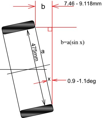
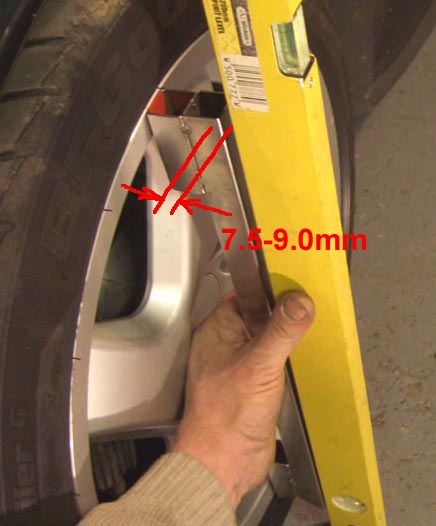
- For camber book figure quotes -0.9 to -1.1deg, which
equates to about 7.5 - 9mm
- gap at the top of wheel rim to plumb spirit level as in
photo below.
- You should be on a flat and level surface and have the
rear suspension at
- normal ride height, also the front seats should be
weighted with 75kg each.
-
- The camber should always be adjusted first because any
movement here will
- also affect the tracking, wheel tracking differences do
not affect camber.
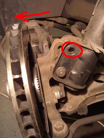
- You can set the camber by loosening the top pinch bolt
(removal not necessary as in pic)
- and bottom bolt and then pulling from the top of the
disc as far as it will go.
- This pulls the axle forging out to its stop in the
slotted upper hole of the strut (ringed)
- and normally this is about right for LC camber. There
seems to be no over adjustment
- because the lower swivel mount plates were extended out
to increase the front wheel base.
-
-
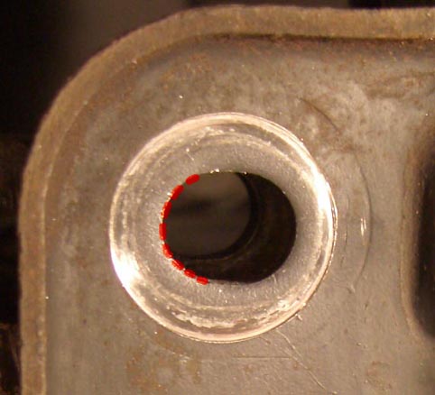
- The reason I removed the bolt completely was to be able
to file the top slotted
- hole in the strut bracket a little longer, about 0.5 -
1.0mm was enough to achieve
- 8mm camber.
-
-
-
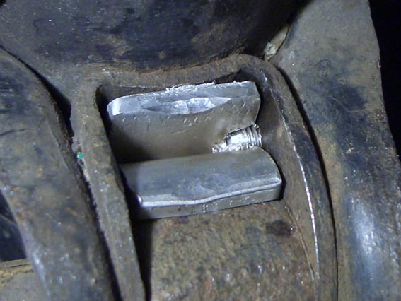
- A problem that has been reported by a few owners was
the camber setting slipping
- back which will destroy perfect tyres in no time. To
prevent this I installed a aluminium
- wedge between the axle forging and strut leg body....btw
thanks Ian M for that thought
- couple years ago........
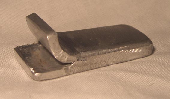
- I would have liked to have them made from a solid
aluminium billet of approx dimensions
- 50mm long, 20mm wide, taper from about 4mm to 5mm (5mm
at the curved end), in the
- event I used 2 bits 3mm thick and seam welded the sides
and formed over at one end so
- it could be removed easily.
-
-
-
- Each side required a slightly differing thickness,
about 0.5mm different overall, and a
- taper of about 0.75-1.00mm, so they were hand filed
until they would just about fit in with
- a few taps of a hammer.
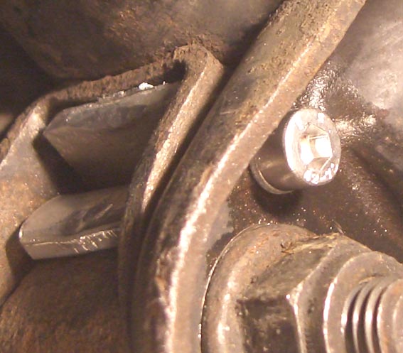
- To secure the wedge in place I drilled and tapped a M5
threaded hole into the side
- of the strut mount plate and a small way into the side
of the wedge. A socket headed
- M5 screw then keeps it from ever falling out.
- Tracking was next, I simply measured the distance
between the inside wheel rims at 3 and
- 9 o'clock positions, here I
am looking for 0.0 - 1.0mm toe in, ie small at front, bigger at rear,
- the movement of the camber had pushed the tracking
about 3-4mm out of alignment.
BACK